
Dr Hugo Ricketts (Unit 1 - Manchester)
Dr Philip Rosenberg (Unit 2 - Leeds)
Instrument Support Level 1
Vaisala DigiCORA® MW41 (400MHz)
ncas-radiosonde-1, ncas-radiosonde-2
sonde
£90,000
150cm x 150cm x 150cm
Up to 80kg
£30
Calendar
Vaisala Radiosonde
[UPDATE] – If you plan to obtain helium for launching radiosondes, please note that there is currently a helium shortage. This could lead to long delays in helium deliveries.
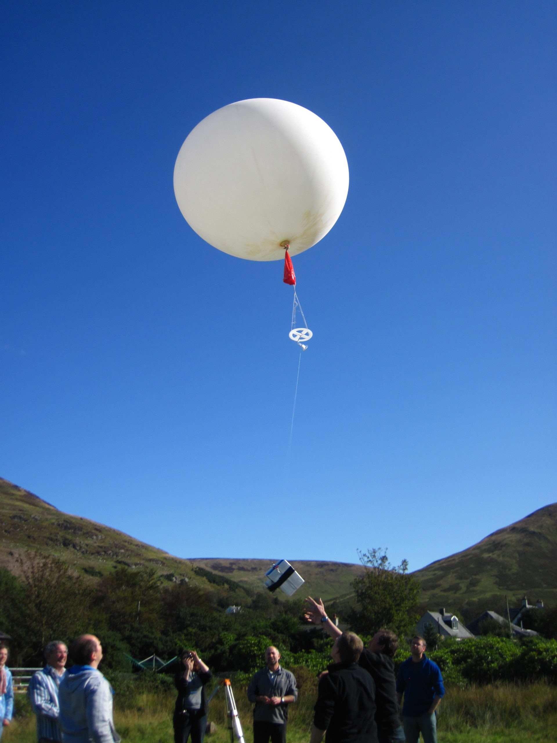
Twice a day, seven days a week, nearly 900 stations around the world release weather balloons into the atmosphere to obtain upper air weather information.
Vaisala sounding products are used by meteorological organizations all around the world to measure weather in the Earth’s atmosphere, from the boundary layer to the upper atmosphere.
The Vaisala DigiCORA® Sounding System simplifies daily synoptic observation by receiving, processing and forwarding meteorological information surely and securely. It is also an excellent tool for research as well as for special measurement campaigns. It gives the user comfortable control over the sounding process by integrating sounding controls, archiving the sounding data, and meteorological message creation. For routine soundings, the system offers a variety of features and allows the desired balance of manual and automatic control.
In addition to the traditional alphanumeric messages, the system software produces the WMO specified BUFR messages. This feature enables users to follow the WMO’s recommendation to move from traditional alphanumeric codes to binary BUFR codes. NCAS has an MoU with the UKMO which allows these messages to be automatically ingested and used in subsequent NWP modelling. We encourage all users to follow the upload procedure.
Two sounding systems are available: one situated in Manchester and one in Leeds, both are compatible with both Vaisala RS92 and Vaisala RS41 sonde family and support the extended sondes recommended by Vaisala. Both systems are 400 MHz variants.
Note:
- AMOF does not supply any equipment to facilitate gas handling and balloon filling.
- Authorisation from Aviation Authorities is, under almost all circumstances, a legal requirement. The user is liable for obtaining all necessary flight clearances.
We have two units available:
- Unit 1 – Manchester
- Unit 2 – Leeds
GPS Antenna
A quadrifilar helix antenna provides good performance in the radiosonde application in terms of sensitivity, radiation gain pattern and multipath rejection.
RF Front End
The satellite signal from the antenna is band-pass filtered and amplified. For maximum tolerance against external RF interference, the first band-pass filter with low insertion loss is placed before the first amplifier. Downconversion of the GPS signal is performed in ASIC, which also adjusts the gain level to be optimal in all conditions.
Search Engine and Correlators
The RF front end ASIC communicates with the second ASIC, which includes baseband parts of the GPS receiver as well as a processor, memories and a set of peripherals. By using an ASIC designed for radiosonde application, maximum performance is achieved at a reasonable cost level.
An important and part of the ccGPS receiver design is the search engine. It is a matched filter that searches in a parallel fashion for all possible satellite ID’s overall possible Doppler frequency bins. It enables probably faster GPS signal acquisition times than any other receiver and requires no information about satellites or GPS time beforehand. By using this approach, it takes less than 20 seconds from sonde power-up until the ground equipment produces valid wind data. For comparison, best time-to-first-fix values for commercial GPS receivers (in cold start mode) are 45 seconds.
The receiver has 12 correlators or channels for signal tracking. Satellite signal C/A code and carrier measurements are processed and packed by an on-chip DSP (Digital Signal Processing) and transmitted to the ground for DGPS calculations.
GPS Position and Wind Calculation
By sending the raw ccGPS measurement data for the ground equipment for further processing, many benefits can be realized:
- Best accuracy is achieved with DGPS (Differential GPS).
- Best reliability due to advanced signal integrity analysis and complex post-processing.
Code (pseudorange) measurements are used for raw positioning. Carrier frequency and phase measurements are used for velocity determination and smoothing of the position data.
GPS Receiver Tracking Capability and Reliability
The GPS receiver is designed to have large “safety margin” in tracking capability. This means that in typical conditions, all visible satellites can be found and tracked down to elevation of 0° and even lower in high altitudes.
This is also seen as reliability and high wind data availability, because signals are continuously tracked once found even in a harsh environment. The dynamic conditions in a sounding do not disturb the receiver due to this application specific ccGPS receiver technology.
One of the sounding series with the latest RS92 GPS prototype was conducted in July, 2002 including 77 test sondes. Based on these, the ccGPS receiver tracking capability is excellent and signal acquisition time very short (few seconds). This specific test was carried out in two locations, Finland and Malaysia. Results are shown in the following table.
| Parameter | Finland | Malaysia |
| Average track gap at launch (<4 sats) |
1.5 s | 0.7 s |
| Average low track count (<4 sats) of available raw data frames | 0.1% | 0.0 % |
| Satellite count, average | 8.9 | 10.7 |
| Soundings with longer than 20s track gap |
1* | 0 |
Although most of the sondes were released almost immediately after being brought out from the shelter, there were no start gaps in most of the soundings, and maximum gap values were less than 15 seconds.
GPS Operation in the Presence of RF Interference
Many sounding stations are located in areas with sources of heavy RF interference, typically different types of radar. This fact was taken into account when designing RS92. Two features guarantee the best possible operation within the presence of strong RF interference:
- Implementation of GPS signal filtering and amplifying. Out-of-band signals are filtered before amplifying giving the receiver high tolerance against RF interference.
- Separate Watchdog function that monitors the system and resets it in case of system malfunction. In extreme conditions (e.g. close vicinity of strong pulse radar), RF interference may cause jamming of the whole system. Watchdog circuitry reactivates the system causing only a few seconds of missing data.
The performance of the sonde has been tested at multiple sites, in various global locations. The sounding site in Malaysia has a radar in close proximity, causing RS80 GPS malfunction and data loss. However, there was no sign of the radar interference with RS92 while the reference RS80 sonde was strongly affected by the radar.
Another site in Europe had an air surveillance pulse radar with 1 MW pulses. When the sonde was placed in the beam with 20-30 m distance from the dish, the system jammed but recovered after only a few seconds. When the sonde was out of the beam, it tracked GPS satellites normally. A test sounding was performed so that the sonde was released within 100 meters distance from the radar. No interference could be seen in GPS operation even when the sonde was in the radar beam.
GPS Accuracy
By using differential GPS, many error sources common to both receivers are eliminated. This means better accuracy for navigation. Position and velocity measurement accuracy is tested in static tests and in double soundings with RS90-AG sonde, which is proven to produce very high accuracy velocity data, when the sufficent number of satellites is available. Preliminary uncertainty (accuracy) results are shown in the table 3.
Table 2. Preliminary RS92 DGPS navigation accuracy.
| Positioning accuracy, horizontal | 10 m |
| Positioning accuracy, vertical | 20 m |
| Velocity measurement accuracy | 0.2 m/s |
The current height calculations is based on pressure measurement, although the Vaisala ccGPS enable also height calculation using GPS data. The feasibility of the GPS height calculation is under evaluation.
Digital Data Transmission
Transmitter functions are mainly performed in ASIC. This circuit includes data coding, modulation, mixing with RF and D/A conversion. The transmission is stable and narrow band due to the use of temperature compensated crystal oscillator and on-chip synthesizer.
The sonde processor controls and monitors the transmitter functions. In the case of low battery voltage, or if the transmitter is out of lock, the processor shuts off the transmitter to prevent transmitting on an incorrect frequency.
The data is first Gaussian filtered and its modulation type is GMSK, which is used for example in GSM mobile phones. This approach uses spectrum efficiently and with advanced receiver technology, it is possible to reduce the sonde output power, while telemetry range performance and data availability remains excellent.
RS92 GPS sondes are designed to be compliant with the proposed ETSI standard for digital radiosondes (ETSI EN 302 054-1).
Data Contents
All measurement data is transmitted to the ground station for processing and analysis. The data set includes sonde diagnostics and identification data, PTU measurements data, GPS measurement data, sensor calibration data and additional sensor data.
Error Detection and Error-Correcting Coding Methods
All data is protected with CRC-16 (16-bit cyclic redundancy checksum). Transmission errors can be reliably detected, and only valid data is passed to the user.
A test flight with 32 Radiosondes was performed at Vaisala using DigiCORA III, RB21 antenna, URR20 and UPP210A radio and RS92. The test showed even without using any error-correction coding algorithms, an average of 1.4% missing raw data due to telemetry. This result is regarded as very good for radiosonde telemetry conditions.
A complex error-correcting coding scheme, called Reed-Solomon, is used in the RS92 sonde. Reed-Solomon coding makes it possible to fix most of the errors that occurred during data transmission. It is thus possible to use a lower output power in the sonde and still have even higher reliability telemetry link, or in other words, lower bit error rate.
Use of Reed-Solomon error-correction coding feature is available only in new Vaisala radio receiver products. Although the system performance and data availability is high with the current URR and UPP receiver system, it is recommended to use RS92 sondes with the new DigiCORA III incorporating the new Vaisala radio receiver. This way the user will achieve the highest possible data availability and quality.
PTU Performance
The RS41 sonde makes use of improved temperature and humidity sensors and no longer measure pressure directly. Where the sonde is also measuring winds pressure is determined from GPS derived altitude and a standard atmospheric model of the atmosphere.
Temperature Measurement
The small size of the sonde Thermocap® temperature sensor construction minimizes the response time (lag) and the effects of solar and infrared radiation. The test results of the sensor in the RS92 transducer construction show consistent performance.
The high accuracy calibration unit, Vaisala CAL4, is used for the sensor calibration. The accuracy test is performed in a simulation chamber. All reference instruments used for calibration and testing are traceable to national or international standards.
Pressure Measurement
The RS41 – SG default base model sonde does not measure pressure directly. The pressure is determined from GPS height, launch conditions, and the American standard atmospheric model.
Users wishing to ensure direct measurement of pressure are advised to use the RS41 – SGP.
Silicon micro-machined Barocap® pressure sensor has already demonstrated excellent performance in RS90 radiosonde use. The small size and the efficient compensation method against ambient temperature change enable small measurement deviation even during most dramatic temperature changes.
Humidity Measurement
The humidity measurement accuracy is dependent on such factors as calibration accuracy, sensor stability, time response, and solar radiation.
One subject of special interest is the humidity sensor performance in the presence of external contaminants during storage. The operation principle of radiosonde humidity sensors is based on the water molecule absorption. If the sensor is made sensitive enough for detailed humidity sensing; it will also be sensitive to other so-called contamination molecules. This can yield to low bias humidity reading, if not properly taking care of. One method to control the contaminants is to cover the sensor with seal and proper desiccant, as utilized in RS80 radiosonde family packaging
Another method is to remove the possible contaminants by substantial sensor preheating before sensor factory calibration and repeating the preheating prior to the sonde launch. The original calibration can be recovered despite any contamination that occurs during storage.
In the calibration repeatability test, the transducer units are calibrated twice. The differences between both runs are calculated. Repeatability is determined as the standard deviation of differences between two successive repeated calibrations, at k = 2 confidence level.
Operational Requirements
- Permissions:
- Under almost all circumstances the launching of radiosondes will require permission from the relevant aviation authorities. In the UK this is the CAA and they will issue a NOTAM to air traffic two weeks before the commencement of the activity. Applications to CAA can only be made 28 days before the commencement of the activity.
- CAA contact details: 020 7453 6599 or email ausops@caa.co.uk
- Parachutes:
- If launching in the UK use of a parachute is a legal requirement.
- Public Liability Insurance:
- Users will be required to prove they have public liability insurance before the system can be signed out.
- Met Sensors:
- At the point of launch, the software will require the user to input a number of meteorological observations. The four that are compulsory are temperature (°C), relative humidity (%), wind speed (m/s), and wind direction (°). The user will need to supply instruments to measure these.
The only component of the system that requires calibration is the sensors in the RS92 ground check and the RS92 & RS41 sonds themselves.
Ground check temperature and humidity sensors are replaced once a year or sooner if required.
Vaisala has developed the CAL-4 calibration standard. As a CAL-4 calibrated radiosonde, the RS41 offers national meteorological services the world’s highest level of PTU (pressure, temperature, relative humidity) measurement performance. Furthermore, the code correlating GPS technology of the RS41-SGP supports national upper-air programs with continuous wind data availability at high resolution.
Consumables
- Balloons:
- Totex and Pawan are the two main manufacturers of meteorological balloons. Totex balloons can be bought via Vaisala and Hoskin Science while Pawan balloons can be bought online from balloon news. The user will also need to supply the means to tie the neck of the balloon when filled.
- String is recommended but many users choose to use cable (zip) ties.
- Parachutes
- In many countries a parachute will be required: the Totex 5710-05 and 5012-05 are suitable for 300g payloads (weight 70g, descent rate 3.6 – 3.8 m/s) while the 160V-05 and 160-05 are suitable for 1000g payloads (weight 180g, descent rate 3.8 – 4.0 m/s).
- The RS41 sonde weighs 150-200g with the dry cell battery option however when using ozone sonde the weight increases to around 900g.
- Vaisala and Hoskin Science are the main suppliers.
- The Rocketman range of parachutes are available through balloon news – these are a general purpose balloon that can be adapted to any payload weight.
- Balloon filling kit
- We do not provide either gas regulators or the means by which to fill a balloon.
- Helium and hydrogen can both be used to fill meteorological balloons but it is recommended that HELIUM be the gas of choice even though it can be difficult to get hold of and is more expensive than hydrogen.
- The gas in most cases will be supplied in pressurised cylinders (200 bar) and a two-stage regulator should be used to facilitate the safe filling of a balloon.
- The thread on a gas cylinder will vary from country to country so care will need to be taken to ensure the regulator has the correct matching thread.
- Regulators are also gas specific: it is not advisable to use a regulator specified for one type of gas with a different gas. In the UK a suitable regulator can be found here.
- In order to ensure the balloon ascends at the desired rate either a known volume of helium must be dispensed or the balloon filled so that reaches neutral buoyancy with a particular payload: other information provided details on how to determine the volume of helium required. Hoskin Science sell a balloon filling kit which consists of a weighted nozzle: the weight of this nozzle can be adapted to meet individual payload requirements and when the balloon is neutrally buoyant with the nozzle attached the balloon contains sufficient gas. The more accurate way is to use a gas meter that allows the user to see exactly how much gas has entered the balloon. A standard domestic methane gas meter is used by ARM facility scientists.
- Sondes
- RS41 family of sondes can only be bought directly from Vaisala
- Gas
- Helium or helium balloon gas is available from both BOC and also from Air Liquide. These suppliers can provide the high pressurised standard cylinders but also offer a convenient low pressure, but small volume cylinder as well. These smaller cylinders are also readily available online from Amazon, party balloon suppliers, and most Calor gas retailers. How many cylinders you may require will depend on the size of the balloon used and also the volume in the cylinder: the L type BOC cylinder contains 9m3 of gas. In the UK high-pressure cylinders are standardised.
- Met Sensors
- At the point of launch the software will require the user to input a number of meteorological observations. The four that are compulsory are temperature (°C), relative humidity (%), wind speed (m/s), and wind direction (°). The user will need to supply instruments to measure these.
Costs
- Instrument Insurance
- This system must be insured by the user for £90K.
- Public Liability Insurance
- We are not liable for any damage or injury arising from the deployment or operation of this instrument when unattended by the instrument scientist.
- Shipping Expenses
- The user is liable for all costs arising from the shipping of the instrument both to and from a deployment.
- IS T&S
- The user is responsible for coving the travel and subsistence expenses of the instrument scientist while attending the instrument.
Shipping Unit 1 (based in Manchester)
The system when packed ready for shipping consists of two flight cases
Box 1: RS41 configuration (RS92 configuration available)
- Sounding processing subsystem, ground check set, sounding laptop, GPS and RF antennas, digital barometer, power adapters and cables
- Shipping dimensions: 80 cm (L) x 55 cm (D) x 30 cm (H)
- Shipping weight: 27.5 kg
Box 2
- Tripod (including antenna mounts), antenna cable, UK multi plug adapter
- Shipping dimensions: 130 cm (L) x 50 cm (D) x 30 cm (H)
- Shipping weight: 36.5kg
Shipping Unit 2 (based in Leeds)
The system when packed ready for shipping consists of a single flight case.
- Signal processing unit, GPS & RF antennas, ground station (including desiccant), Sounding laptop (power supply and network cables in laptop bag), UK power cables for signal processing unit and ground check unit, 50m system signal cable.
- Tripod, gps antenna mount
- Shipping dimensions: 130 cm (L) x 52 cm (D) x 68 cm (H)
- Shipping weight: 52 kg
The signal processing unit, sounding computer, and ground check station need to be powered and sheltered from weather.
The antenna tripod can be no more than 50m from the signal processing unit sounding computer, and ground check station.
Approximately 1m of bench space is required for the signal processing unit, sounding computer, and ground check station and each of these will need access to 240VAC power.
The antenna require as great a view of the sky as possible. Sites in valleys or in the vicinity of mountains often lose ‘sight’ of a sonde early due to obstruction.
Although it is convenient for the balloon to be filled near to where the sounding computer is located, this is not a limiting factor for site selection.
Filling the balloon is made easier if shelter can be provided.
The launch area should be clear of obstructions.
The launch area should provide sufficient space for the movement of gas cylinders and for the gas cylinders to be secured.
Cylinder handling and use of compressed gas
- Compressed gas cylinders are required for the filling of balloons. Those handling and using such cylinders should seek training in their correct handling and usage.
Manual handling
- When in its packing case it is recommended that two people be used when lifting. Once unpacked a single person can easily move and deploy the system. A cable is required to run from the sounding station to the antennas users should be aware that both the instrument and the power cable constitute a trip hazard and users should take appropriate actions to minimise this.
Electric safety
- Under no circumstances should any attempt be made to open up the main body of the instrument.
Attended operation
- Once the sonde is launched there is no requirement for the system to be attended during operation from a safety standpoint.
Permission to launch
- The user should be in possession of flight permission, or a clear statement of exemption. In the UK this is the NOTAMS document and is issued by the CAA. In some UK locations the CAA will require the user to contact ATC on a specific number prior to flight. Users must follows CAA instructions. See Operational Requirements for instructions on how to obtain permission to fly in the UK.
Latex
- Meteorological balloons are made from latex. Latex can induce severe allergic reaction.
When unpacked and deployed:
- Antenna tripod foot print : 150 cm (L) x 150 cm (W) x 150 cm (H) (250 cm legs fully extended)
- Weight (not including shipping case): 10 kg
- Sounding station foot print (PC, signal processing unit, ground check ): 100 cm (L) x 45 cm (W) x 45 cm (H)
- Weight (not including shipping case): 70 kg
Power
- PC, signal processing unit, ground check station: 100 – 240VAC (at 47 – 63 Hz)
- Consumption (entire system): ~ 5W
Environmental
- Antenna operation temperature: -40°C to 45°C
- PC, signal processing unit, ground check station operation temperature: 0°C to 45°C
Cables
- A 50m twin signal cable runs from the signal processing unit (and attenuator) to the antennas
- Signal processing end
- black connector connects to the GPS input on the signal processing unit
- silver connector screws in to the terminal on the attenuator block
- attenuator connects to the antenna in on the signal processor (only one possible socket the connector will fit)
- Antenna end
- connector marked GPS screws direct into the GPS antenna
- remaining connector screws in to the grey box on the antennal mount
- 30cm patch cable connects RF antenna to this box
- Signal processing end
- Cat 5 Ethernet cable connects signal processing (LAN 1) to laptop
- Serial cable connects laptop serial 9 pin D connector to the similar connector on the ground station
- Ground cable on attenuator block should be attached to a suitable ground
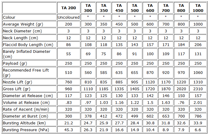
There are a range of balloons used in meteorology and they are named by weight: that is the weight of unfilled balloon. The RS92 sonde weighs about 280 to 290g and RS41 around 140g – the algorithms inside the sonde that correct for heating due to solar radiation assume an ascent rate of 5.3 m s-1.
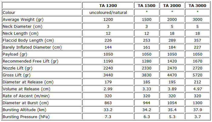
Each balloon has different properties. The properties for each balloon have been calculated for the totex range of balloons and provide the user with approximate bursting altitude and volume of helium required to launch a standard RS92. It is advised that the TA 1200 be used for ozone sonds.
Properties for TA200 – TA1000.
Properties for TA1200 – TA3000.
Field Data
- Operationally while in the field the user will parse the sounding using the sounding station software on the supplied laptop. This produces the default EDT file which is a tsv formatted text file, the user can name this file as they see fit.
Archive data
- Data is provided in NetCDF files following the AMOF data standard
- Files contain a single sounding.
- Instrument name is
- ncas-radiosonde-1
- ncas-radiosonde-2
- The data product(s) associated with this instrument:
- Example data file