
Instrument Support Level 2
METEK MRR2 Micro Rain Radar
ncas-mrr-1
rain-lwc-velocity-reflectivity, size-concentration-spectra
£27,000
80cm x 60cm x 85cm, 17kg
See page for details
£20
Calendar
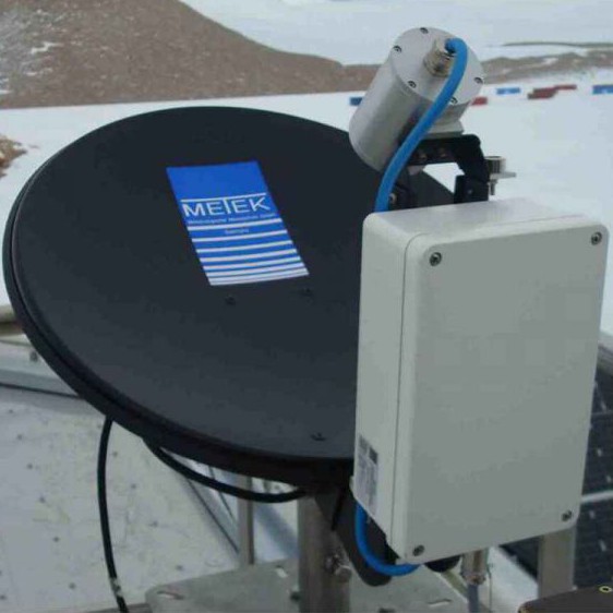
Micro Rain Radar
The MRR Micro Rain Radar is a compact 24 GHz FM-CW-radar for the measurement of profiles of drop size distributions and – derived from this – rain rates, liquid water content and characteristic falling velocity resolved into 30 range gates. Due to the high sensitivity and fine temporal resolution very small amounts of precipitation – below the threshold of conventional rain gauges – are detectable.
The large scattering volume (compared to in situ sensors) means that statistically stable drop size distributions can be derived within a few seconds. The droplet number concentration in each drop-diameter bin is derived from the backscatter intensity in each corresponding frequency bin. In this procedure, the relation between terminal falling velocity and drop size is exploited.
Automatically controlled antenna heating allows operation under icing conditions. Typical applications include the unattended long-term measurement of rain, real-time calibration of weather radar, and monitoring of the melting zone.
Transmit power: 50 mW
Frequency: 24.23 GHz
Beam width: 1.5°
Averaging interval: 10 – 3600s
Height resolution: 10 – 200 m
Number of range gates: 30
Detection threshold (height 500 m, height resolution 100 m, time resolution 10s): 1 mm / hr
Antenna heating: 230 VAC
Interface: RS232,LAN
Power: 24VDC, 25W
Weight: 6 kg
A full description of the instrument operational principles can be found in the MMR User Manual.
The system requires to be either connected directly to a host PC (supplied) or via the internet (serial to network convertor supplied) to the host PC for control and data logging.
Time stamping of the data is derived from the host PC. It is advised that the system clock is synchronised at regular intervals and UTC used.
The host PC can be remotely operated through VNC. This is password protected and users will be issued with a password when taking delivery of the instrument.
Although antenna heating is not always required the heating power cable must be installed.
The system also has a bubble level indicator tilt to aid in levelling the instrument when deploying.
This instrument needs no special license to operate.
The derived volume reflectivity, drop size distribution and all integral parameters depend proportional on the radar calibration constant C. It is determined by comparison with in situ rain rate measurements in selected environmental conditions. Its uncertainty is estimated to be ±10 %.
The temporal stability of C has been investigated by evaluating the echo from a well-defined target (triple reflector) and by changing the transmitter/receiver temperature over a range of about 30 K. The observed variation of echo power was less than 10 %. (These measurements cannot be performed with the standard signal processing software because echoes from fixed targets are suppressed.) The instrument undergoes a manufacturer’s “health check” annually where the radar is recalibrated.
Continual monitoring during a deployment and system diagnostics allows the IS to determine if the system is operating optimally or requires manufacturer servicing and intervention.
Costs
- Instrument Insurance
- This system must be insured by the user for £27K.
- Public Liability Insurance
- We are not liable for any damage or injury arising from the deployment or operation of this instrument when unattended by the instrument scientist.
- Shipping Expenses
- The user is liable for all costs arising from the shipping of the instrument both to and from a deployment.
- IS T&S
- The user is responsible for coving the travel and subsistence expenses of the instrument scientist while attending the instrument.
Shipping
The system when packed ready for shipping consists of two flight cases.
- Case 1
- radar antenna, antenna heater power cable, host PC, signal cable.
- Case 2
- Radar control and transceiver, power and signal junction box, serial cable, serial to ethernet converter, manuals.
Before installation, the site must be checked for its suitability for rain measurements. There must be a free field view of at least 10° around the zenith angle over the radar.
Nearby transmitters (base stations of mobile phones, broadcast towers, radars) can cause interference although they operate nominally at different frequency bands. If operating in the vicinity of such transmitters, a simple metallic screen or larger object (container) obscuring the direct line of sight to the interfering source can help.
Deployment in the vicinity of electric machinery should also be avoided due to their potential for EM interference which is difficult to screen.
For measurements at very low heights, care must be taken to minimise the wind field turbulence in the required lower levels caused by nearby buildings, trees, masts, etc.
When comparing with in-situ rain sensors the exposure of the antenna to the free wind field is not favourable.
General requirements
- Only the antenna unit including RCPD, Transceiver and control cable are designed for outdoor operation. All other components, e.g. the junction box and PC, must be installed in a weather protected environment with temperatures within 5 – 40°C.
- If cables are laid on the field, a cable conduit is recommended.
- All cable connections should be protected by strain-reliefs.
- Use only the original connectors.
- Operating of the MRR-2 requires a 230 VAC mains supply, with fuse protection of 8 A (slow) minimum.
- To minimise disruption due to power loss use of a UPS is recommended.
- The MRR antenna requires fixing to a vertical pole
- Ø max. 49 mm, length min. 30 cm
For ease of operation, it is advised to ensure that there is network infrastructure to hang the instrument on.
At sites where animal activity is likely precautions will need to be taken to prevent chewing\pecking of cables.
There are no known health hazards originating from the emitted electromagnetic radiation of 50 mW. Nevertheless, you should take care that everybody keeps out of the beam above the antenna (parabolic dish) when it is in operation.
Manual handling
- When in its packing case it is recommended that two people be used when lifting.
- Once out of the case the instrument requires one person to lift or move it.
- Two cables have to run to the instrument and so users should be aware that both the instrument and the cables constitute a trip hazard and users should take appropriate actions to minimise this.
Electric safety
- To operate the MRR-2 a mains voltage of 210-240 VAC is needed for the power supply.
- Improper handling can be dangerous.
- Only competent and instructed persons should work with this system or with parts of it. Under no circumstances should any attempt be made to open the main body of the instrument.
- The power supply/signal processing unit that is separate from the instrument can be opened if problems occur but only once they have been disconnected from both the supply and the instrument.
- Only appropriately qualified persons should attempt to fault find these units.
Attended operation
- There is no requirement for the system to be attended during operation from a safety standpoint.
When unpacked and deployed the MRR has the following physical characteristics.
RCPD with radar module
Operating frequency: 24.230 GHz
Operating mode: FMCW
Modulation: 1.5 – 15 MHz
Output power: 50 mW (+17 dBm) (antenna foot point)
Spurious emission: < -80 dBm/MHz (antenna foot point)
2nd Harmonic: -37 dBm
ITU-Designation: 30M0N0N
Power supply: 24 VDC / 1A
Antenna
Type: parabolic offset antenna
Diameter: 600 mm
3 dB Beamwidth: approx. 1.5 °
Gain: 40.1 dBi
Junction box / power supply:
Input Voltage: 230 VAC (50 .. 60 Hz) or 24 VDC
Output Voltage: 24 VAC / 1.5 A
Dimensions: 205 x 145 x 65 mm
Weight: 1.3 Kg
Antenna Heating
Power supply: 230 VAC (50 .. 60 Hz)
Power output: approx. 200w
Complete System:
Weight: 17.5 Kg
Dimensions: 800 x 600 x 850 mm
Field Data
- The instrument produces a range of out files and all are text format.
- The user can download (but not delete) this data from the instrument but it should be noted that this data will not have been quality controlled.
Archive data
- Data is provided in NetCDF files following the AMOF data standard
- Files contain no more than 24hr of data.
- Instrument name is
- ncas-mrr-1
- The data product(s) associated with this instrument:
- v1.1
- Vertical dimension uses “index”.
- For profiling instruments (not the radiosondes) the altitude variable and profile variables have dimensions of time and index
- The version should be used if the altitude variable is likely to vary over the duration of the file.
- rain-lwc-velocity-reflectivity
- size-concentration-spectra
- v2.0
- Vertical dimension uses “index”.
- For profiling instruments (not the radiosondes) the altitude variable and profile variables have dimensions of time and index
- The version should be used if the altitude variable is likely to vary over the duration of the file.
- rain-lwc-velocity-reflectivity
- size-concentration-spectra
- Example data file
- v1.1