
Instrument Support Level 2
Campbell Scientific
ncas-energy-balance-1, ncas-energy-balance-2
radiation, soil
£10,000
5 m x 2 m x 1m:. 10kg
See page for details
£10
Calendar
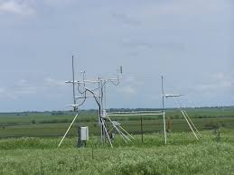
Surface Energy Balance Station
The Energy Balance Station comprises
- Campbell Scientific CR3000 logger (with 1GB expansion card)
- 3 x Campbell Scientific 107 Temperature Probe.
- 3 x Campbell Scientific 253 Soil Matric Potential Block
- 3 x Hukseflux HFP01SC Self Calibrating Soil Heat flux plates
- Radiation
- Unit 1
- Hukseflux NR01 4 Component Net Radiation Sensor
- Unit 2
- 2 x Kipp & Zonen CGR 4 Pyrgeometer (Upwelling and Downwelling)
- 2 x Kipp & Zonen CMP 22 Pyranometer (Upwelling and Downwelling)
- Unit 1
- Garmin 18 PC GPS
- 2 x adjustable trips and aluminium tube with mounts for radiometers
The logger interface is networked and the user is also provided with a laptop pre-loaded with the software needed to access system data.
There are two complete systems available.
The Surface Energy Balance is the exchange of energy between the Earth’s surface and the overlying atmosphere.
This exchange involves four important processes, namely:
- Absorption and Emission of ’natural’ electromagnetic radiation by the surface.
- Thermal Conduction of heat energy within the ground.
- Turbulent transfer of heat energy towards or away from the surface within the atmosphere.
- Evaporation of water stored in the soil or Condensation of atmospheric water vapour onto the surface.
The radiometers are serviced before deployment or every two years: whichever is the sooner.
The Campbell Scientific Logger are re-calibrated every 5 years
Costs
- Instrument Insurance
- This system must be insured by the user for £10K and covers loss, theft or damage to the instrument: damage is that over and above general wear and tear. The system has been designed to be rugged and autonomous. Even so, the end-user must respect the fact that the system is a precision optical instrument that must be treated with great care.
- The user is responsible for the instrument from the time it leaves the AMF to the time it is returned and signed off as in an acceptable operating condition by the IS: this will be done as soon as is possible on its return.
- Public Liability Insurance
- The AMOF is not liable for any damage or injury arising from the deployment or operation of this instrument when unattended by the IS.
- Shipping Expenses
- The user is liable for all costs arising from the shipping of the instrument both to and from a deployment.
- IS T&S
- The user is responsible for coving the travel and subsistence expenses of the IS while attending the instrument.
Shipping
The system when packed ready for shipping consists of four boxes of various size and weight
Please contact the facility for more details
The stem requires mains electricity. The system will accept either 240 or 110 VAC but it is recommended on safety grounds that 110 VAC is supplied.
The logging system is self-contained but itis recommended that if possible the logger be connected to a network as this will allow remote access, monitoring, and control.
Manual handling
- A procedure appropriate to lifting a heavy object should be used when lifting any of the boxes. This procedure consists of bending at the knees while keeping your back straight and upright.
- Cables kept away from pathways; held overhead height if necessary.
Electric safety
- Check all module casings and cables are in good condition before switching on.
- Attach all cables before switching on at the mains. All equipment electrical safety tested.
Attended operation
- There is no requirement for the system to be attended during operation from a safety standpoint.
COSHH
- Not applicable
Radiometer Mount
- 30 cm – 2 m height range on tripods
- 5 m support pole between tripods
Power
- 24Vdc power supply provided
- This takes 240V or 110VAC
- 5 m DC power cable to system interface
- 110V 16 A Cform connector on supply
- 110V (16 A) (yellow) to 240V (16A)(blue) pigtail
System interface
- Contains logger
- Connections to all sensors
- Network Connection
Field Data
- The instrument produces a range of out files and all are text format.
- The user can download (but not delete) this data from the instrument but it should be noted that this data will not have been quality controlled.
Archive Data
- Data is provided in NetCDF files following the AMOF data standard
- Files contain no more than 24hr of data.
- Instrument name is
- ncas-energy-balance-1 (Hukseflux)
- ncas-energy-balance-2 (Kipp & Zonen)
- The data product(s) associated with this instrument:
- Example data file