
Instrument Support Level 2
Campbell Scientific CS 135 Ceilometer
ncas-ceilometer-1
aerosol-backscatter, cloud-base, cloud-coverage
£20,000
100 cm x 33 cm x 32 cm. 32kg
120 cm x 45 cm x 45 cm. 58kg
£20
Calendar
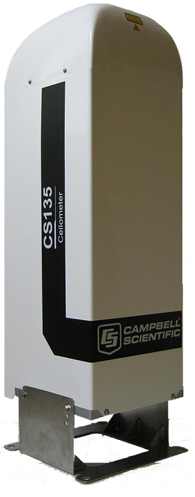
Ceilometer
The CS135 LIDAR Ceilometer measures cloud height and vertical visibility for meteorological and aviation applications. Using LIDAR (light detection and ranging) technology, the instrument transmits fast, low-power laser pulses into the atmosphere and detects back-scattered returns from clouds and aerosols above the instrument.
The CS135 employs a single lens design to increase optical signal-to-noise ratio over other instruments. One half of the lens is used for the transmitter and the other for the receiver with total optical isolation between them. This allows it to have exceptional performance with low altitude overlap between the transmitter and receiver allowing lower altitude measurement and integrating larger optics into a compact package. The optics are immune to damage from direct sunlight. The optics are also immune to damage from direct sunlight.
This approach, along with state-of-the-art electronics, provides a powerful and stable platform from which to measure cloud height and vertical visibility to high accuracy. With a rugged environmental enclosure that protects the instrument from the harshest conditions, the CS135 measures the atmosphere with high stability and repeatability.
The CS135 can be tilted up to 24º. Cloud heights are automatically corrected. A small tilt is an important feature as it allows the CS135 to resist high levels of reflection from large raindrops and frozen particles that can impair a vertical sensor. Tilting to 24º means that it can be operated anywhere in the world without the sun shining into the lens and resulting in missing data.
The CS135 provides information on cloud height, sky condition (up to five layers) and raw backscatter profiles. It has a unique stratocumulus calibration capability for accurate measurements of scatter coefficients.
Reliable range measurement is assured by cross checking two internal clocks.
The CS135 complies with CAA and ICAO guidance and meets or exceeds all recommendations and specifications. (This includes CAP437, CAP670, and CAP746).
Reporting Range: 0 to 10 km (0 to 32,808.4 ft)
Minimum Reporting Resolution: 5 m (15 ft)
Hard Target Range Accuracy: ±0.25%, ±4.6 m
Reporting Cycle: 2 to 120 s
Cloud Layers Reported: Up to four layers
Sky Condition: Up to five layers with cover in oktas according to WMO requirements for SYNOP and METAR codes
Vertical Visibility: Reported when no clouds selected
Laser Wavelength: 912 nm (±5 nm)
Eye Safety Standard: Class 1M
Maximum Wind Speed: 55 m/s
The operating principle of the ceilometer is based on measurement of the time needed for a short pulse of light to traverse the atmosphere from the transmitter of the ceilometer to a backscattering cloud base and back to the receiver of the ceilometer. The general expression connecting time delay (t) and backscattering height (h) is h = ct/2, where c is the speed of light. With c = 2.9929 x 10⁸ m/s, a reflection from 7620 m will be seen by the receiver after t = 50.9 μs.
Generally, particles at all heights backscatter light. The instantaneous magnitude of the return signal will provide information on the backscatter properties of the atmosphere at a certain height. From the return signal, information about fog and precipitation, as well as cloud, can be derived. Since fog and precipitation attenuate the light pulse, the cloud base signal will appear lower in magnitude in the return echo. However, the fog and precipitation information also provides data for estimating this attenuation and computing the necessary compensation, up to a limit. In its normal full – range operation, the ceilometer digitally samples the return signal every 67 nanoseconds (ns) from 0 to 50 μs, providing a spatial resolution of 10 m from ground to 7700 m distance. This resolution is adequate for measuring the atmosphere since visibility in the densest clouds is of the same order.
For safety and economic reasons, the laser power used is so low that the noise of the ambient light exceeds the backscattered signal. To overcome this, a large number of laser pulses are used, and the return signals are summed. The desired signal will be multiplied by the number of pulses, whereas the noise, being random, will partially cancel itself. The degree of cancellation for white (Gaussian) noise equals the square root of the number of samples; thus, the resulting signal – to – noise ratio improvement will be equal to the square root of the number of samples. However, this processing gain cannot be extended endlessly since the environment changes, and, for example, clouds move.
The volume backscatter coefficient, β(z), represents the portion of the light that is reflected back towards the ceilometer from a distance z (e.g., by water droplets). It is obvious that the denser a cloud is, the stronger the reflection will be. The relationship can be expressed as
β(z) = k*σ(z)
where k = “constant” of proportionality and σ = is the extinction coefficient (i.e., the attenuation factor in a forward direction).
The extinction coefficient relates to visibility in a straightforward manner. If visibility is defined according to a 5% contrast threshold (World Meteorological Organization definition for Meteorological Optical Range [MOR]), equals daylight horizontal visibility), then
σ = 3 / V
where V = MOR visibility (5 % contrast).
The “constant” of proportionality, k, also called theLidar Ratio, has been subjected to a lot of research. Although the Lidar Equation can be solved without knowing its value, it must remain constant with height if accurate estimates of the extinction (or visibility) profile are to be made.
It has been found that in many cases, k can be assumed to equal 0.03, tending to be lower in high humidities, to 0.02; and higher in low humidities, to 0.05. However, in precipitation of various kinds, k will have a wider range of values. Assuming a value 0.03 (srad-1) for k and visibility in clouds being in the range 15 – 150 m, gives the range of value for β:
β = 0.0006 – 0.006 m-1srad-1 = 0.6-6 km-1srad-1
Any fog, precipitation, or similar obstruction to vision between ground and cloud base may attenuate the cloud base signal and produce backscatter peaks that far exceed that from the cloud. Virtually any backscatter height profile is possible, up to some physical limits. To distinguish a significant cloud return signal, the attenuation of fog, precipitation, etc., has to be taken into account by normalizing with regard to extinction. The profile thus obtained is proportional to the extinction coefficient at various heights and enables the use of fairly straightforward threshold criteria to determine what is cloud and what is not.
By assuming a linear relationship between the backscatter and extinction coefficient according to the previous formula and that the ratio, k, is constant over the range observed, it is possible to obtain an extinction coefficient profile through a mathematical computation. This is also called inverting the backscatter profile to obtain the extinction coefficient profile and answers the question: “What kind of extinction coefficient profile would produce the backscatter profile measured?”
No assumption as to the absolute value of the ratio, k, needs to be made if k is constant with height. The assumptions that have to be made are fairly truthful, and in any case, accurate enough for the purpose of cloud detection. Likewise, the inversion is also independent of several instrumental uncertainties including transmitted power and receiver sensitivity.
An estimate of vertical visibility can easily be calculated from the extinction coefficient profile because of the straightforward extinction-coefficient-to-visibility relationship, provided that a constant contrast threshold is assumed. Visibility will simply be that height where the integral of the extinction coefficient profile, starting from the ground, equals the natural logarithm of the contrast threshold, sign disregarded.
Tests and research have, however, shown that the 5% contrast threshold widely used for horizontal measurement is unsuitable for vertical measurement if values close to those estimated by a ground-based observer are to be obtained. The ceilometer uses a contrast threshold value
that, through many tests, has been found to give vertical visibility values closest to those reported by ground-based human observers. A wide safety margin is obtained with regard to pilots looking down in the same conditions since the contrast objects, especially runway lights, are much more distinct on the ground.
Although the system operates in RS232 mode a serial to ethernet converter has been installed within the body of the ceilometer. The ceilometer is thus fully networkable and can be installed on most networks: the logging laptop supplied has the software installed that is required to find and connect to the ceilometer using the serial to ethernet converter and a manual to guide you through the process is also supplied on the logger.
The Ceilometer is configured to output a data message (type 2) at 10-second intervals. The logging software time stamps the data messages using its internal clock (set to synch daily to an NTP time server) and saves them to file: New files are opened every hour and files are saved in a daily directory.
This instrument needs no special licence to operate.
Internal housekeeping messages provide the Instrument Scientist with the operational health of the system: when these indicate that the unit is not operating optimally it is returned to Campbell for service. The Instrument Scientist also quality controls data and, if requested, can monitor the system during a deployment – faults are found quickly and attended to.
The calibration is also verified by tilting the ceilometer at a hard target at a known distance. A comparison with MPL heights during low cloud situations can also be informative. The hard target testis performed by removing the measurement unit from the shield, placing the unit horizontally, turning off tilt angle correction, and detecting the return from a solid object of known distance at least 300 m from the ceilometer.
Consumables
The user will need to supply both power and networking cables.
- Network: requires to be terminated at the instrument end by a Bulgin Buccaneer IP68Cat5e RJ45 connector.
- Power: requires a 16A 240V 3P connector at the instrument end.
A PC\laptop system will be supplied by AMF to connect and log the data.
Costs
- Instrument Insurance
- This system must be insured by the user for £20K.
- Public Liability Insurance
- The AMOF is not liable for any damage or injury arising from the deployment or operation of this instrument when unattended by the IS.
- Shipping Expenses
- The user is liable for all costs arising from the shipping of the instrument both to and from a deployment.
- IS T&S
- The user is responsible for coving the travel and subsistence expenses of the IS while attending the instrument.
Shipping
The system when packed ready for shipping consists of a single flight case – integrated wheels. The case contains the Ceilometer, logging laptop, cables.
- Shipping dimensions:
- 120 cm (L) x 45 cm (D) x 45 cm (H)
- Shipping weight:
- 58kg
The Ceilometer should be deployed on a surface that is not liable to flooding.
Although requiring two people to move, the system will require securing to a surface to prevent movement due to wind impact. It should also be located on a secure site to avoid theft and vandalism.
For ease of operation it is advised to ensure that there is network infrastructure to hang the instrument on.
A shelter or laboratory space is required to house the logging laptop.
At sites where animal activity is likely precautions will need to be taken to prevent chewing\pecking of cables.
Eye safety
- This system contains a class 1M category laser and is eye safe for all conditions of use.
Manual handling
- When in its packing case it is recommended that four people be used when lifting. Once out of the case the instrument requires two people to lift and or move it.
- At least one cable has to run to the instrument and so users should be aware that both the instrument and the power cable constitute a trip hazard and users should take appropriate actions to minimise this.
Electric safety
- Under no circumstances should any attempt be made to open the main body of the instrument. The power supply and UPS units that are separate to the instrument can be opened if problems occur but only once they have been disconnected from both the supply and the instrument. Only appropriately qualified persons should attempt to fault find these units.
Attended operation
- There is no requirement for the system to be attended during operation from a safety standpoint.
Temperature Range:
- -40° to +60°C (-40° to +140°F)
Humidity Range:
- 0 to 100% RH
IP Rating:
- IP66 (NEMA 4x)
Dimensions:
- 100 x 33.0 x 31.6 cm (39.4 x 13.0 x 12.4 in.) including base
Shipping Dimensions:
- 120 x 45.0 x 45.0 cm (47.2 x 17.7 x 17.7 in.)
Weight:
- 32 kg (71 lb) without cables.
- 25 kg (55 lb) without cables, outer cowling, and enclosure.
- Shipping Weight:
- 58 kg (127.9 lb)
Power:
- 110, 115, 230 Vac ±10%,
- 50 to 60 Hz,
- 470 W maximum
Interfaces:
- Data Interfaces: Ethernet
- Maintenance Interfaces:
- USB 2.0 (USB 1.1 compatible)
- Baud Rate Interfaces: 300 to 115200 bps
Compliance:
- Laser Safety Compliance: EN60825-1:2001
- Electrical Safety Compliance: EN61010-1
Cables:
- Power:
- The user will need to supply a 3 core power cable of appropriate length for the deployment.
- This needs to be terminated by a 16A 240V 3P (2P + E) connector at the instrument end.
- Signal:
- The user will need to supply either a standard cat5 ethernet cable of the appropriate length for the deployment.
Field Data
- The instrument produces a range of out files and all are text format.
- The user can download (but not delete) this data from the instrument but it should be noted that this data will not have been quality controlled.
Archive Data
- Data is provided in NetCDF files following the AMOF data standard
- Files contain no more than 24hr of data.
- Instrument name is
- ncas-ceilometer-1
- The data product(s) associated with this instrument
- v1.1
- Vertical dimension uses “index”.
For profiling instruments (not the radiosondes) the altitude variable and profile variables have dimensions of time and index - The version should be used if the altitude variable is likely to vary over the duration of the file.
- aerosol-backscatter
- Vertical dimension uses “index”.
- v2.0
- Vertical dimension uses “altitude”.
For profiling instruments (not the radiosondes) the altitude variable has dimensions of altitude and the profile variables have dimensions of time and altitude - The version should be used if the altitude variable does not vary over the duration of the file.
- aerosol-backscatter
- Vertical dimension uses “altitude”.
- v1.1
- Example data file