
Instrument Support Level 3
Vaisala, CT25k
Not Applicable
Calendar
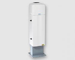
Vaisala CT25k LIDAR Ceilometer
The CT25k LIDAR Ceilometer measures cloud height and vertical visibility for meteorological and aviation applications. Using LIDAR (light detection and ranging) technology, the instrument transmits fast, low-power laser pulses into the atmosphere and detects back-scattered returns from clouds and aerosols above the instrument.
The operating principle of the ceilometer is based on measurement of the time needed for a short pulse of light to traverse the atmosphere from the transmitter of the ceilometer to a backscattering cloud base and back to the receiver of the ceilometer. The general expression connecting time delay (t) and backscattering height (h) is:
h = ct/2,
where c is the speed of light. With c = 2.9929 x 10⁸ m/s, a reflection from 7620 m will be seen by the receiver after t = 50.9 μs.
Generally, particles at all heights backscatter light. The instantaneous magnitude of the return signal will provide information on the backscatter properties of the atmosphere at a certain height. From the return signal, information about fog and precipitation, as well as cloud, can be derived. Since fog and precipitation attenuate the light pulse, the cloud base signal will appear lower in magnitude in the return echo. However, the fog and precipitation information also provides data for estimating this attenuation and computing the necessary compensation, up to a limit. In its normal full – range operation, the ceilometer digitally samples the return signal every 67 nanoseconds (ns) from 0 to 50 μs, providing a spatial resolution of 10 m from ground to 7700 m distance. This resolution is adequate for measuring the atmosphere since visibility in the densest clouds is of the same order.
For safety and economic reasons, the laser power used is so low that the noise of the ambient light exceeds the backscattered signal. To overcome this, a large number of laser pulses are used, and the return signals are summed. The desired signal will be multiplied by the number of pulses, whereas the noise, being random, will partially cancel itself. The degree of cancellation for white (Gaussian) noise equals the square root of the number of samples; thus, the resulting signal – to – noise ratio improvement will be equal to the square root of the number of samples. However, this processing gain cannot be extended endlessly since the environment changes, and, for example, clouds move.
The volume backscatter coefficient, β(z), represents the portion of the light that is reflected back towards the ceilometer from a distance z (e.g., by water droplets). It is obvious that the denser a cloud is, the stronger the reflection will be. The relationship can be expressed as:
β(z) = k*σ(z)
where k = “constant” of proportionality and σ = is the extinction coefficient (i.e., the attenuation factor in a forward direction).
The extinction coefficient relates to visibility in a straightforward manner. If visibility is defined according to a 5% contrast threshold (World Meteorological Organization definition for Meteorological Optical Range [MOR]), equals daylight horizontal visibility), then σ = 3 / V where V = MOR visibility (5 % contrast).
The “constant” of proportionality, k, also called the Lidar Ratio, has been subjected to a lot of research. Although the Lidar Equation can be solved without knowing its value, it must remain constant with height if accurate estimates of the extinction (or visibility) profile are to be made.
It has been found that in many cases, k can be assumed to equal 0.03, tending to be lower in high humidities, to 0.02; and higher in low humidities, to 0.05. However, in precipitation of various kinds, k will have a wider range of values. Assuming a value 0.03 (srad-1) for k and visibility in clouds being in the range 15 – 150 m, gives the range of value for β:
β = 0.0006 – 0.006 m-1srad-1 = 0.6-6 km-1srad-1
Any fog, precipitation, or similar obstruction to vision between ground and cloud base may attenuate the cloud base signal and produce backscatter peaks that far exceed that from the cloud. Virtually any backscatter height profile is possible, up to some physical limits. To distinguish a significant cloud return signal, the attenuation of fog, precipitation, etc., has to be taken into account by normalizing with regard to extinction. The profile thus obtained is proportional to the extinction coefficient at various heights and enables the use of fairly straightforward threshold criteria to determine what is cloud and what is not.
By assuming a linear relationship between the backscatter and extinction coefficient according to the previous formula and that the ratio, k, is constant over the range observed, it is possible to obtain an extinction coefficient profile through a mathematical computation. This is also called inverting the backscatter profile to obtain the extinction coefficient profile and answers the question: “What kind of extinction coefficient profile would produce the backscatter profile measured?”
No assumption as to the absolute value of the ratio, k, needs to be made if k is constant with height. The assumptions that have to be made are fairly truthful, and in any case, accurate enough for the purpose of cloud detection. Likewise, the inversion is also independent of several instrumental uncertainties including transmitted power and receiver sensitivity.
An estimate of vertical visibility can easily be calculated from the extinction coefficient profile because of the straightforward extinction-coefficient-to-visibility relationship, provided that a constant contrast threshold is assumed. Visibility will simply be that height where the integral of the extinction coefficient profile, starting from the ground, equals the natural logarithm of the contrast threshold, sign disregarded.
Tests and research have, however, shown that the 5% contrast threshold widely used for horizontal measurement is unsuitable for vertical measurement if values close to those estimated by a ground-based observer are to be obtained. The ceilometer uses a contrast threshold value that, through many tests, has been found to give vertical visibility values closest to those reported by ground-based human observers. A wide safety margin is obtained with regard to pilots looking down in the same conditions since the contrast objects, especially runway lights, are much more distinct on the ground.
Internal housekeeping messages provide the Instrument Scientist with the operational health of the system: when these indicate that the unit is not operating optimally it is returned to Campbell for service. The Instrument Scientist also quality controls data and, if requested, can monitor the system during a deployment – faults are found quickly and attended to.
The calibration is also verified by tilting the ceilometer at a hard target at a known distance. Comparison with MPL heights during low cloud situations can also be informative. The hard target testis performed by removing the measurement unit from the shield, placing the unit horizontally, turning off tilt angle correction, and detecting the return from a solid object of known distance at least 300 m from the ceilometer.
Archive Data
- Data is provided in NetCDF files following the AMOF data standard
- Files contain no more than 24hr of data.
- Instrument name is
- ncas-ceilometer-2
- The data product(s) associated with this instrument:
- aerosol-backscatter
- v1.1
- Vertical dimension uses “index”.
For profiling instruments (not the radiosondes) the altitude variable and profile variables have dimensions of time and index - The version should be used if the altitude variable is likely to vary over the duration of the file.
- aerosol-backscatter
- Vertical dimension uses “index”.
- v2.0
- Vertical dimension uses “altitude”.
For profiling instruments (not the radiosondes) the altitude variable has dimensions of altitude and the profile variables have dimensions of time and altitude - The version should be used if the altitude variable does not vary over the duration of the file.
- aerosol-backscatter
- Vertical dimension uses “altitude”.
- v1.1
- cloud-base
- cloud-coverage
- aerosol-backscatter
- Example data file